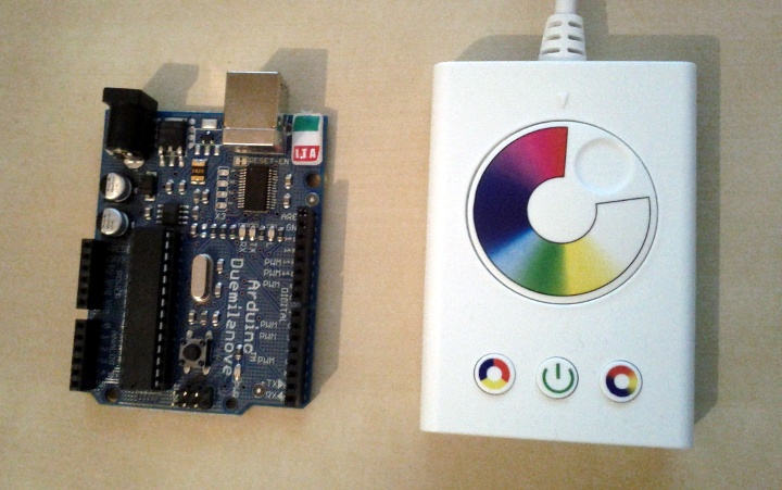
I went to IKEA recently and could not resist to buy two of these awesome DIODER lights for 20 € each. One set consists of 4 bars with 9 RGB LEDs each, a power supply and a control unit to set the color. Of course there are also a bunch of cables and some accessories to attach the bars somewhere, so it’s quite a good deal after all. The bars can either be connected in a series but also in some sort of star topology.
The control unit allows you to set a fixed color using a rotary control or to switch between two programs that automatically change the color of the light over time. Honestly the whole thing turned out to be quite boring after a very short time, but still i love these RGB LED bars. The only consequent option was to decamp one of those control units to see what can be done with it, preferably finding a way to connect an Arduino to that damn thing.
Analysis
A quick analysis reveals the following very simple structure of the unit. Note that you can also find some details in christian’s DIODER++ hack.
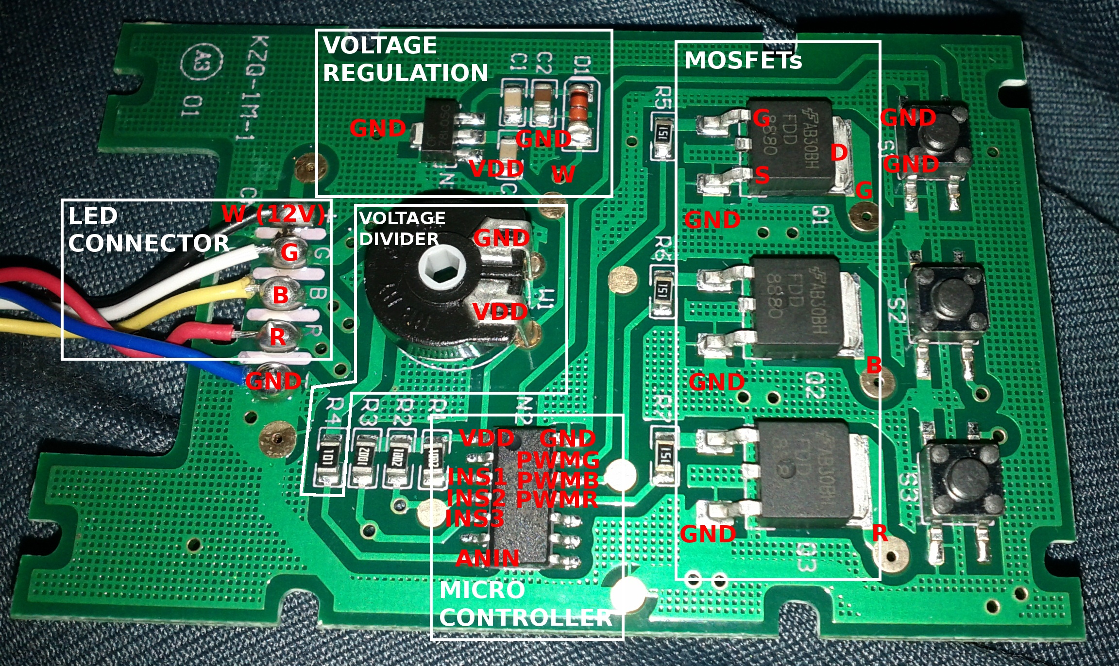
The four upper wires of the LED connector go directly into the LED bars, while W and GND are directly connected to the anode and cathode of the 12V power supply. R, B and G come from the MOSFET drains.
The voltage regulation generates a stable 5V voltage VDD to power the micro controller.
The voltage divider is physically connected to the rotary control and is used to generate the voltage for the analog input ANIN of the micro controller. Depending on that voltage, the LEDs will change their color.
The MOSFETs operate as switches here. Using the 5V from our micro controller output (PWMG, BWMR and PWMB) and a very low current, we can switch the 12V and the higher current of the power supply to the LEDs (R, B and G).
It’s the heart of the control unit: the micro controller. It reads the voltage ANIN and turns it into a color generating a three-channel PWM signal (PWMG, BWMR and PWMB) that drives our MOSFETs. Also the switches INS1, INS2 and INS3 are connected to the micro controller to turn it on or off and to select the automatic color changing programs.
To get a feeling for the operation point of the used LEDs and the power consumption, I measured different currents at full intensity on all channels (white). According to a label on the LED bar, one bar consumes 1.25W at 12V DC, which is about 104mA. The measures show that this is quite the case (I_W):
I_G (9 LEDs) = 20 mA
I_G (18 LEDs) = 40 mA
I_G (27 LEDs) = 60 mA

I_B (9 LEDs) = 27 mA
I_B (18 LEDs) = 55 mA
I_B (27 LEDs) = 78 mA

I_R (9 LEDs) = 53 mA
I_R (18 LEDs) = 100 mA
I_R (27 LEDs) = 145 mA

I_W (9 LEDs) = 100 mA
I_W (18 LEDs) = 200 mA
I_W (27 LEDs) = 300 mA
I_W (36 LEDs) = 390 mA
I_W (45 LEDs) = 480 mA
I_W (54 LEDs) = 560 mA
I_W (63 LEDs) = 635 mA
I_W (72 LEDs) = 710 mA
For the individual color channels, I only measured up to three LED bars (27 LEDs), but the DIODER comes with four of them (36 LEDs). I successfully ran 8 bars (72 LEDs) with the original power supply that is shipped with the DIODER. The voltage of the supply drops from 11.95V to 11.75V when there are 8 bars hooked-up, which is still okay since it is only specified to provide up to 420mA at 12V DC. However the power supply becomes very hot with 8 bars connected. You should not run it with 72 LEDs for such a long time!
Approach One: Only put the Micro Controller out of Work
The first and very simple approach to hack the control unit is to bypass the built-in micro controller and connect the PWM pins of an Arduino to the board. You can easily solder your own connectors to PWMG , PWMB and GND. Unfortunately there is no convenient way to do this for PWMR. However if you still plan to do so it should not be a big deal if you mess up the pin next to PWMR since it is unused.
I actually investigated this approach and it works quite well. You only have to ensure not to run the built-in micro controller and the Arduino at the same time to avoid short circuits. So for this very simple approach you only need 4 wires to hook-up to your Ardunio!
Approach Two: Replace the entire Control Unit
From the analysis we have learned that we basically only need some MOSFETs to drive the LEDs, the MOSFETs and some resistors to limit the current. These are six very small and cheap pieces of hardware to be acquired in order to keep the control unit untouched completely. You can even avoid soldering if using a breadboard.
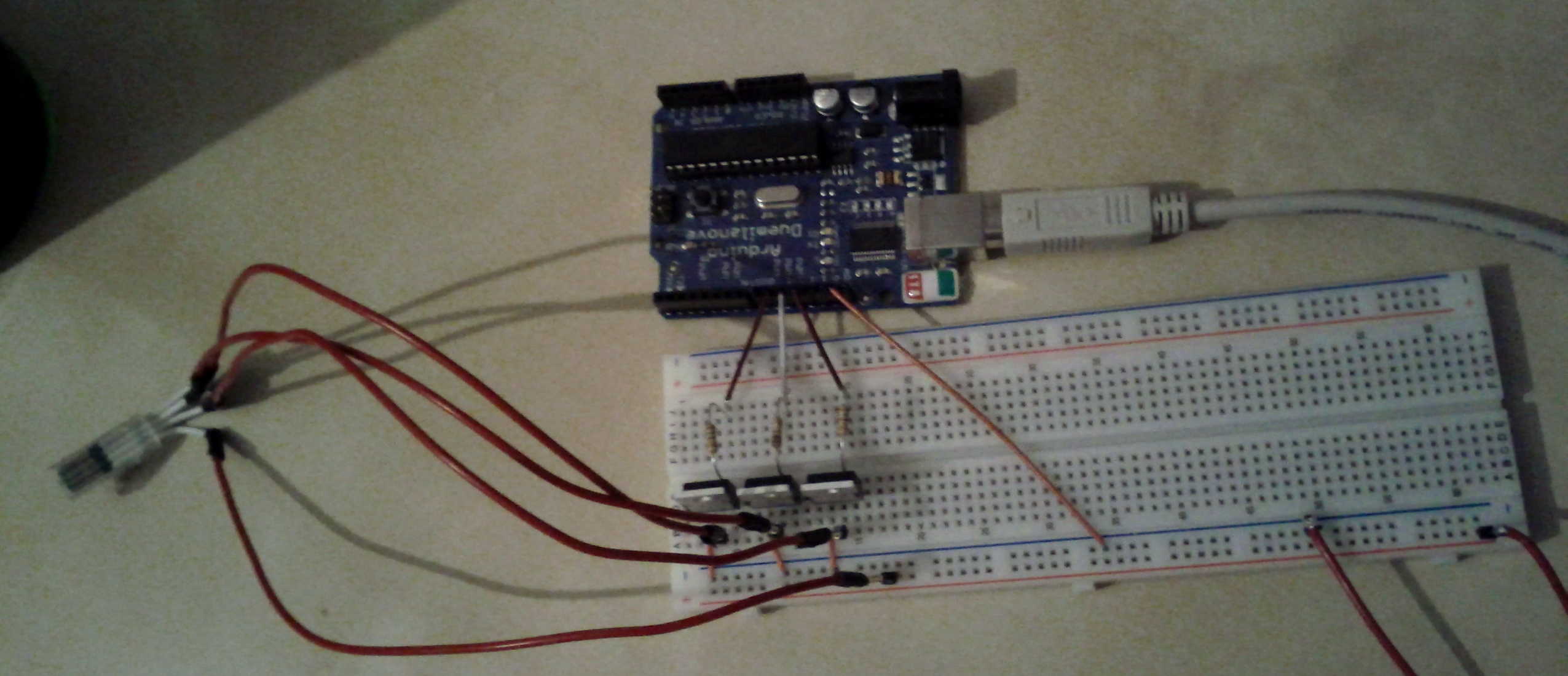
As seen on the picture, you need to craft a small cable that can be connected to the LED bars. You can simply cut one of the numerous enclosed cables and attach some connectors to it.
The wiring is the same as on the original board: each MOSFET drives one LED color channel. The source pins are directly wired to ground, while the gates are connected by a resistor to some of the PWM output pins of the arduino. The drains go to B, G and R of the LED connector. Of course we also need a 12V power source that is connected to the W conductor of the LED connector. Don’t worry: the conductors are labeled on the connector!
Besides the power supply that is shipped with the DIODER, I used BUZ11 MOSFETs and 150Ohm resistors to build the circuit. Just to be sure not to rape the LEDs, I repeated some of the above measures and it looks quite okay:
I_G (9 LEDs) = 21 mA
I_G (18 LEDs) = 40 mA
I_G (27 LEDs) = 57 mA

I_B (9 LEDs) = 28 mA
I_B (18 LEDs) = 53 mA
I_B (27 LEDs) = 75 mA

I_R (9 LEDs) = 53 mA
I_R (18 LEDs) = 100 mA
I_R (27 LEDs) = 145 mA

I_W (9 LEDs) = 95 mA
I_W (18 LEDs) = 177 mA
I_W (27 LEDs) = 247 mA
The Software
Now we have everything wired up so we only need to find some smart ways to control the LEDs. I thought the most eclectic way to do this would be using serial IO and a computer as a source for the control signals. The programs that runs on the Arduino looks as follows. It basically just waits for three bytes to be transmitted on the serial port and writes them as R, G and B values to the PWM output ports.
const int outR = 9;
const int outB = 10;
const int outG = 11;

void setup() {
  Serial.begin(9600);

  analogWrite(outR, 0);
  analogWrite(outG, 0);
  analogWrite(outB, 0);
}

void loop() {
  if (Serial.available() >= 3) {
    analogWrite(outR, Serial.read());
    analogWrite(outG, Serial.read());
    analogWrite(outB, Serial.read());
  }
}
For the PC side I wrote this handy driver class featuring gamma correction for each channel.
class DioderDriver {
  char r,g,b;
  char[] mapR, mapG, mapB;

  Serial serial;

  boolean dummyMode;

  DioderDriver(PApplet parent) {
    dummyMode = (parent == null);

    r = 0;
    g = 0;
    b = 0;

    mapR = linear();
    mapG = linear();
    mapB = linear();

    if (!dummyMode) {
      String portName = Serial.list()[0];
      serial = new Serial(parent, portName, 9600);
    }
  }

  char[] linear() {
    char[] m = new char[256];
    for (char i=0; i<256; i++) {
      m[i] = i;
    }
    return m;
  }

  char[] gammaCorrection(float gamma) {
    char[] m = new char[256];
    for (char i=0; i<256; i++) {
      float x = i / 256.0f;
      float y = pow(x, gamma);
      m[i] = (char)(y * 256.0f);
    }
    return m;
  }

  void update() {
    if (!dummyMode) {
      serial.write(mapG[g]);
      serial.write(mapB[b]);
      serial.write(mapR[r]);
    }
  }
};
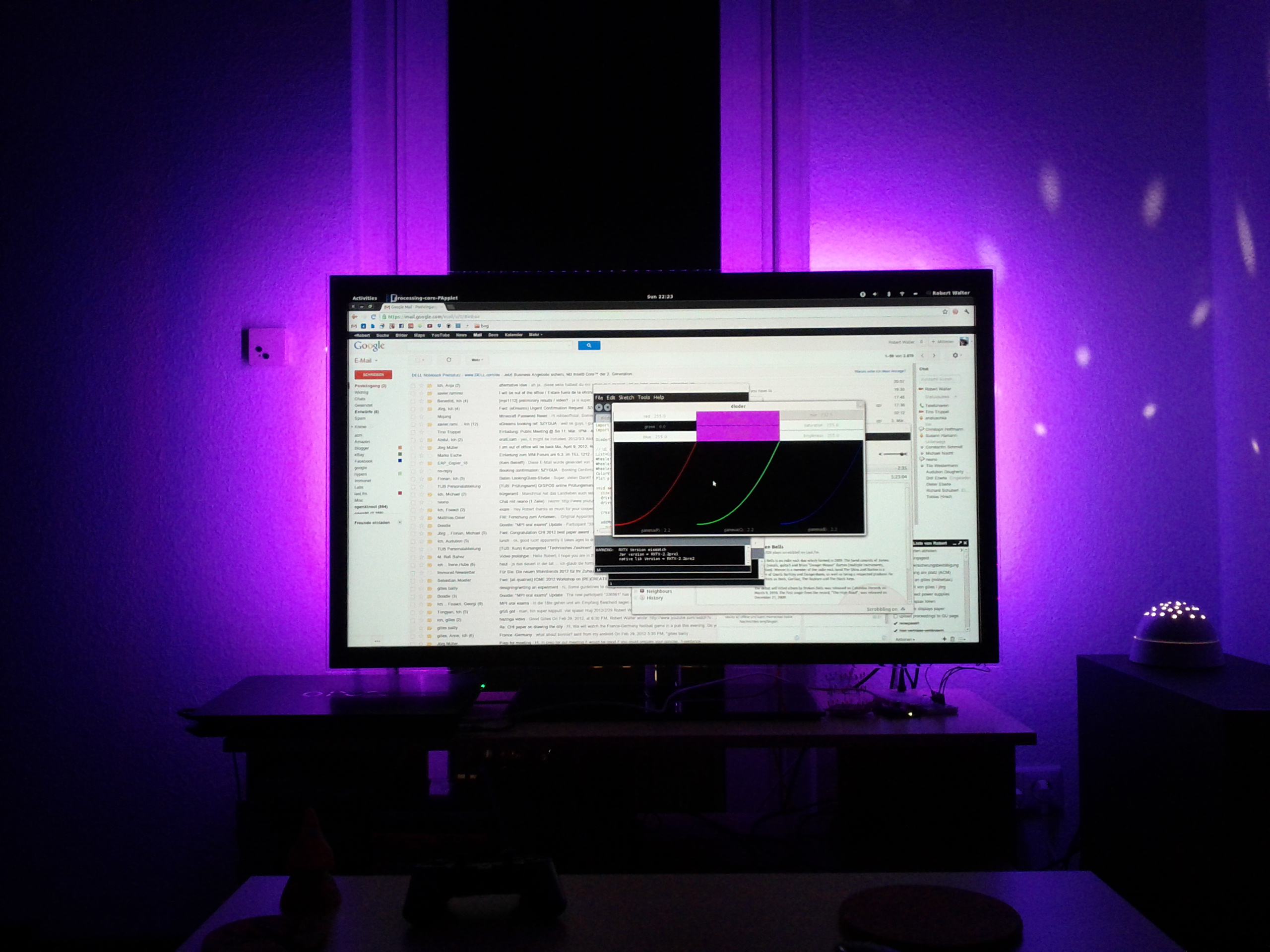
While testing and debugging I wrote a small tool in processing that allows to adjust either the RGB or the HSB color values of the LEDs, as well as the gamma correction curve for each color channel individually.
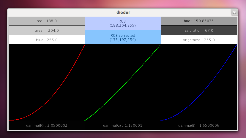
You can download the complete source code of the tool and the driver. To adjust values, point on them with the mouse cursor and spin the mouse wheel.
The video shown above was created with last.fm as an input and a simple spectrum analyzer from a previous post.
